

STAGING
For a layout built for operations, staging is probably one of the most important part of the model. Staging on the Wyoming
Division is in four locations. Following convention, staging is not part of the layout with scenery; it represents distant places
that trains “go to” or “come from” the layout like actors leave and enter a theater stage from the wings. The four locations are
Main Staging on the lower level between Ogden “on” the layout and the Staging Helix, connected to Cheyenne “on” the layout
at its other end
North Platt, Nebraska—adjacent to the main staging is an 5
track stub yard about 17 feet long to hold trains ready to enter
the layout through main staging, up the staging helix, and
heading west through Cheyenne “on” the layout
East Bound Passenger Staging, the 4 tracks joining the east
bound passenger tracks out of Cheyenne. See the photo above
of east Cheyenne
Portland, the staging yard under the main helix accessible via
the OSL.
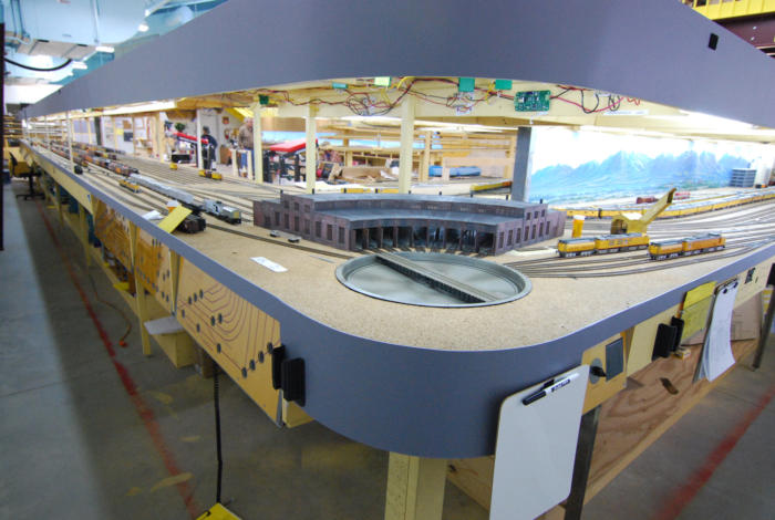
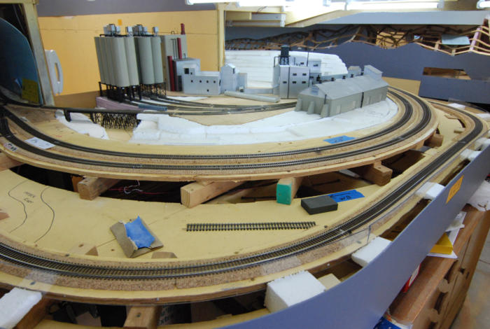
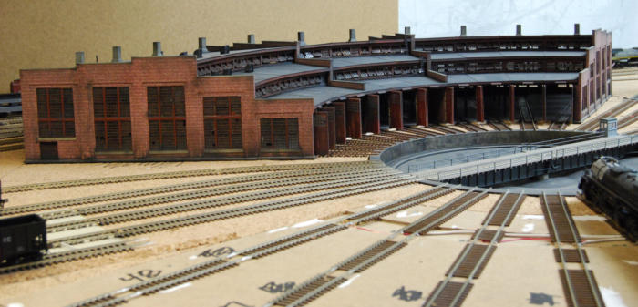
Figure 17 shows the main staging spread out on the lower level
bench to the left. The North Platte staging is just beyond the
Ogden roundhouse and has a yellow UP
Figure 17. Ogden round house with staging to the left and Ogden to the right on the lower level and more panels for
staging and Ogden.
4 unit F set on it. This also shows the 3 staging switch panels to control the Tortoise machines near the roundhouse. To the
right is Ogden “on” the layout, and counting from the bench edge inward are the Locomotive track to the turntable and coal
tower, 4 Ogden Ready tracks, two mains into staging to the west, and 4 passenger tracks in front of the depot with associated
passenger car storage, clean out and provisioning tracks, and the Freight House.
The main staging plus North Platt to the left has over 551 feet of track divided into 5 roughly equal sections for west A/D, west
(beyond Ogden) Passenger staging, unit trains (PFE, soda, coal, iron ore), west (beyond Ogden) classification, and east (east
of Cheyenne or North Platte) staging. All of this is in 31 tracks each long enough for a 30 car train and locomotive, tender, and
caboose, or a 15 car passenger train and locos. The minimum track length for all main line yards is 17 feet on the layout and
in staging, including Portland. Counting Portland the Wyoming Division has about 650 feet of staging, enough for 52 full 30 car
trains, plus the 3 passenger staging tracks and run around track in Cheyenne.
The 3 track east-of-Cheyenne passenger staging yard to simulate destinations to Chicago, Kansas City, St. Louis, etc. (79 feet
of track) is pictured in a photo in the “Photographs Tab.” Those 3 tracks plus a runaround track are connected to the turning
loop on the top of the staging helix.
The Portland yard is under the lower level. It is the origin and destination for OSL trains and is shown in Figures 14 and 19.
The minimum track length for any yard track is 17 feet. Altogether there is room for the storage of 33 complete trains which
can be ready to run at the beginning of an operating session, and that number leaves at least one free track in each staging
section for runaround moves. It is unrealistic to pack the staging that full at the start of or at any time during an operating
session. But for all sessions we have about 25 to 27 trains ready at the start of a session, most in staging, and others
distributed over the layout in Cheyenne, Ogden, Laramie, and Green River. Soon after a session starts there is then ample
room to receive trains back into staging from those that start out on the middle of the layout. Others that start in staging and
leave near the beginning of the session will not begin to arrive back for over an hour. Thus a session will start with ample
trains running and ready to run, and the Staging Yardmaster and his two assistants should not be overwhelmed at any one
time during a session.
OSL
I also designed in a route to Portland, Oregon via the old
Oregon Short Line (OSL) from Granger, Wyoming just west of
Green River. On the Wyoming Division, the OSL junctions with
the mains and immediately becomes a hidden single track
behind and angling down to run under some benches toward
“Portland,” which is another staging yard under the lower level.
The photos on the “Photographs Tab” show the beginning of the
hidden OSL through the “mouse hole,” visible through the
scenery cardboard strips, ¼ of the way from the left in the
middle. The track through the hole is hidden track that takes the
OSL track under a mountain that we have not yet covered with
scenery foam. The hidden OSL runs under the two mains to be
Aspen and Altamont Tunnels under the scenery and around the
edge of the bench end cap on spline/cork roadbed to reverse
the track back
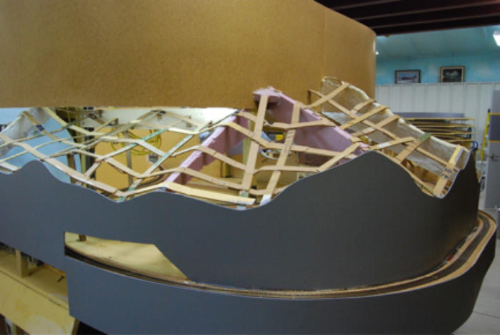
Figure 18. OSL hidden track seen through incomplete scenery. Both mains run under this scenery which is the
mountain through which the Aspen and Altamont tunnels was bored. The hidden track OSL then emerges around the
edge of the lower bench.
toward “Portland.” It winds as hidden track under the lower level
benches for 3 benches, or 168 feet. It can be seen through the
mountain forming cardboard strips on the left side of Figure 18.
The whole Portland yard is at the end of the hidden OSL track,
and it is shown in Figure 19. The edge of the right hand end of
this yard can be seen in Figure 14 as the third layer down.
The Portland staging yard is on a 24 inch wide shelf under the
lower level. The shelf is only 9 ½ inches tall, but the yard can
be easily worked from a Husky rolling stool from Home Depot,
because all work is during pre-staging to make up trains to be
run during a session. The yard is not worked during a session
except to remove trains from it or take trains to it. Reconfiguring
the freights into new trains before sending them out again is
done between sessions.
Figure 19. Portland staging yard shown under lower level.
PARK CITY BRANCH
Figure 20 shows the start of the Park City Branch soon after its junction with Track #2 in Echo, Utah. This is a photo early in
the construction of the hidden track of the Park City Branch. This single track rapidly loses elevation to become a hidden track
under the front edge of the far bench as seen here. Under that bench, on the next aisle, it goes into a 3 track yard and is
terminated beyond that in a 9” turntable. This is the destination for the Park City Local, a one train a session switching job, to
be run out of Ogden to the far left of this bench and back with a stop in Echo to switch cars there. The Local takes all west
bound traffic from Echo including the Ideal Cement cars back to Ogden with it. One of many through Manifest trains will pick
up east bound cars headed away from Echo, Ideal Cement, and Park City left there by the Park City Local to be moved east
toward Cheyenne.
The Ideal Cement plant, Red Devil Brand, is also here, and it can be seen completed in the “Photographs” page.
Lenny made a switch panel for Echo and Park City and the Ideal Cement Company, because the turnouts are hard to reach
here.
Reliance Branch and U. S. Steel Railroad
Rock Springs is a long industrial town on the Lower Level. It is nearly 2 benches long, but the benches are the two shortest
ones due to the location of the main helix. The Rock Springs benches are too narrow to have a yard with all the industries that
we wanted to include. There are 20 industries including 3 UP coal mines, and all are served from the Green River yard around
the bench end cap. There is a Reliance Branch that goes north
from Rock Springs in Wyoming to the Reliance Coal mines, but
on the layout this “north” direction is folded along the east-west
tracks of Rock Springs. We plan on scratch building the steel
coal tipple that still stands in Reliance, Wyoming. We have 3
tracks laid to run under this tipple, which originally spanned 5
tracks.
Also branching off near the end of the Reliance Branch is the U.
S. Steel Railroad that ran to Atlantic City about 70 miles north
and east of Rock Springs. We did not have room to model the
iron ore mines there which shipped ore to the Geneva Steel Mill
sough of Salt Lake City, so we had to make do with a long stub
track that we load 36 ore jennies on and move them from
“Atlantic City” through Ogden and on to staging which stands in
for the steel mill.
Figure 20. Park City Branch hidden track on a grade down to under the lower bench just east of Echo, Utah.
CHEYENNE ROUNDHOUSE
Allen Montgomery built most of the major Cheyenne yard structures built as shown in the previous photos.
Lenny Wyatt scratch built the Passenger House of the Cheyenne roundhouse. The prototype had 20 stalls used for passenger
locomotives only. The Freight House part of the round house was used only for freight steamers, and he will build it eventually,
and it will have approximately twice as many stalls.
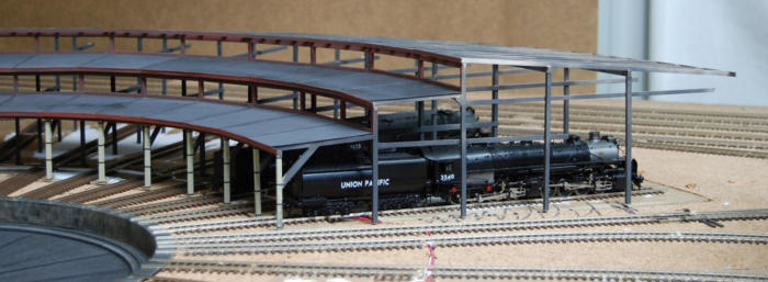
The Passenger House is shown in Figure 21. It has only 11 stalls, but covers the same angle as the prototype. Doing the
entire 20 stalls would have necessitated increasing the outside (and inside) diameter of the house and moving it back from the
turntable pit, or else making the stall tracks cross each other near the pit. Neither alternative was acceptable.
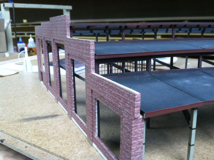
Lenny drew the brick walls and
the window frames on
AutoCad. He printed out the
brick walls on plain paper on
an ink jet printer, and glued
them to the flat walls made
from 1/8” plywood. The brick
support posts at the building
corners and between sections
were made by gluing a second
layer of plywood to the wall
and then wrapping the printed
brick paper around the wall
and each post. Using
Figure 21. Passenger House, part of Cheyenne’s split roundhouse, being test fit in Cheyenne on the upper bench.
Figure 22. Passenger house brick detail.
a great deal of care and more
patience than I could summon,
he managed to get the crease
of the folded paper exactly into
the inner bent corners or
around the outside corners
with the preprinted brick lined
up perfectly just as they would
appear if make by brick layers.
The window frames were a
size that we could not find
commercially and some had a
pattern of 4 - 5 - 4 vertical
glass panes wide, but drawing
them on AutoCad was pretty
simple. He then had them
laser cut from plywood at a
commercial shop in Phoenix.
The next two show the
completed Passenger House.
Figure 23. Side and front of the Passenger House in Cheyenne on the upper bench.
Figure 24. Rear of Passenger House in Cheyenne on the upper bench.
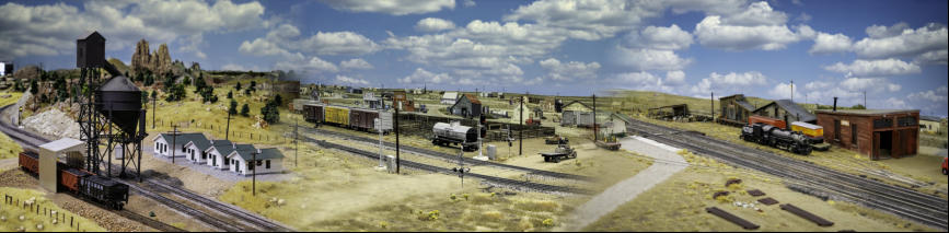
The next Photo shows the layout from the mezzanine looking out over about one half of the layout. The other half of the layout
is shown in Figure 7. This half shows Rawlins and Sinclair, Wyoming left, the barren prairie, the Red Desert, on the left with a
center siding between the two main tracks and Cheyenne yard all on the upper level. Part of Rock Springs, Wyoming and the
east end of the Green River yard is visible on the lower level.
OTHER VIEWS OF THE LAYOUT
Many photos are presented on the layout throughout construction and up until progress to mid-April, 2015 in the “Photographs”
page.
DESIGN OF THE FOUR CARD OPERATING SYSTEM
As a historical society, the main purpose of the Wyoming Division Layout is to be a project to study and demonstrate the
history of the late steam era railroad, the Union Pacific. The Society also has on display a large collection of photographs by
noteworthy railroad photographers from the mid Twentieth Century and art work by artists, and Union Pacific advertising
brochures, posters, and calendars as well as memorabilia from that era.
Operations
As stated earlier present day model railroad operations is running trains with a purpose, as if the operators were a full railroad
industrial company trying to make a profit by delivering freight and passengers for customers in a timely manner. The
objective of study and demonstration of 1957 UP operations is largely fulfilled by the study and creation of a workable model
railroad operating system that simulates the prototypical running of the 1957 UP, and then using that model system to
demonstrate in real time model railroad operations by real persons (volunteer modelers, rail fans, and observers) to produce
realistic, but workable model operations. Naturally, the part time model railroad “employees” cannot devote anywhere near the
amount of time to model operations as the working real railroad employees did to their jobs. It is a matter of 4 to 6 hours a
month of volunteer work versus 40 or more hours per week of real work to earn wages to feed a family—it is volunteer hobby
versus full time employment. The Wyoming Division HO model has achieved a high degree of realism by the following efforts.
•
Design of Operating System: Operations should be governed by Rule 251D with Track Warrant Authority to occupy a
track. ABS Signals should be used to facilitate this.
o
Passengers should be moved according to a timetable schedule and stop for passengers at the same stations as
the real railroad did
o
The passenger trains that are run should be fair facsimiles of the trains UP ran in 1957
o
Passenger trains should have the highest priority on the road (Superior to all other trains)
o
Freight movements should be in railroad cars such as to simulate waybills
o
From a distance the freight movements should appear fairly random and not repeatable and cyclical
▪
Some cars should move west (or east) one move and turn back east
▪
Others should continue a few or many moves in the first direction before turning
▪
Not all cars have to move each session
▪
Some cars may move more than one time per session
▪
Less than Carload Lot (LCL) cars should be common, moving from depot and freight houses to other depots
and freight houses with only brief stops (1-2 hours) at each before being moved along. The short stops are
sufficient to hurriedly unload part loads and load new part loads for the next station up the line.
▪
Some cars should be in “captive” service moving back and forth between the same two locations.
▪
Some groups of cars may all have the same point of origin and same destination, in which case they may be
moved together as one “car” in a block. If they all carry the same commodity, one waybill may do; if not, and if
they are different types of cars for different types of freight, the waybills are needed, but may be assumed to
“be in the caboose” like they were in the real trains.
▪
The freight cars should be identifiable as empty or loaded or LCL (partially loaded). Only then may it be
determined when they are ready for new service.
▪
When a car is unloaded it should tend to be moved back toward the home territory of the railroad that owns it,
otherwise excess demurrage (per diem charges) would incur to each railroad on which it spends time. Empty
cars cost; they do not earn money.
▪
Some cars travel short distances (in local service) while others make long trips (transcontinental service)
•
For a high degree of realism these elements are needed
o
MOW trains (Maintenance of Way) to repair the track and get in the way of for-profit trains
o
Bad order cars—model cars break down just like real ones. A two pronged approach to this
problem might be
o
Some cars limp into the next station to be “bad-ordered” and left on a RIP (repair in place) track,
either repaired while loaded or unloaded and the cargo (and waybill) moves along in a different car,
or
o
The car is so badly damaged that its cargo has to be transferred to a new car out in the country at a
siding where it was left by its original train.
o
One of the railroad’s biggest customers was itself—much cargo was shipped to and from the
railroad into shops and out of storehouses. The same may be said of MOW supplies, steel,
hardware, cement, timbers, etc.
o
Safety should be the primary concern of all the “employees” of the model, just like the real railroad. This implies
▪
Slow speeds
▪
To simulate heavy loads for which it is hard to change speeds
▪
To insure adequate room to stop if necessary
▪
To have a hierarchy for trains, so faster and more important trains may pass slower ones, which tend to be
less time sensitive.
▪
For safety it was necessary to know where every train was at any one time, but in 1957 without computers or
many radios this was done by verbal and written reports of local depot personnel (a tower operator) phoning
the centrally located Dispatcher dozens or hundreds of mils away. The Dispatcher kept track of trains on a
very large sheet of paper called a Train Sheet, and on it he tabulated the movement of each train in its own
column, with the lines of the column representing landmarks, depots or other fixed locations a known distance
apart.
o
Profit is also important to the model railroad in mimicking the real road.
▪
The tradeoff between fast trains with a given investment of crew wages and locomotive resources and slower,
longer and heavier trains should be considered, like the operating department had one priority (more
tonnage/man hour and /locomotive (fuel, etc.)—slower trains, and the marketing department had another—fast
trains)
▪
Trains must not be held up in one place for extended periods of time. Delays can cause spoilage of perishable
goods (fruits and vegetables), inhumane and illegal violation of the 28 hour rule for resting, exercising, and
feeding and watering stock every 28 hours.
▪
Refers should also be iced, because there were few mechanical refrigerator cars
▪
Provision for fuel, water, sand, and to dump ashes should be made at intervals that replicate the real railroad.
Also for icing refrigerator cars.
▪
Extra locomotive help in the form of helper locomotives may be needed up the grades
▪
Lighter and more economical front end power may be used on the flatter prairie.
o
In short the model operating system should ideally be able to simulate everything the real railroad normally does.
•
The Wyoming Division Historical Society’s HO model simulates all the above with a simple 4 card system
o
Head End or Single Trick Car Cards: For all cars not in blocks
▪
Every car has a card, that tells it where it came from, where it is to be delivered, whether it is full, empty, or
LCL and when it was loaded (if it started out empty) or when it was unloaded (if it started out full).
▪
LCL cars are always marked “LCL” and presumed nearly full and in a constant process of being loaded and
unloaded.
▪
Each car card has many lines, and
•
each line shows the above information.
•
Cars may be moved on or held at the end of each line (end of each move). The move ends when the
“unloaded” or “loaded” box is checked or dated.
•
The car card simulated the waybill only as far as From-To-Loaded/Empty-Unloaded/Emptied. The nature
of the load is assumed from the car type (cantaloupes are unlikely to be hauled in tank cars); no real
railroader gives a hang what is in the car as long as it is not Haz Mat (hazardous material). Pains must
be made not to send a tank car to a steel company unless some justification may be made for such a
move.
o
Block Cards: one card is for n cars,
o
n is written on the card to show how may cars the block contains
▪
for only the first and last cars in the block the Road Name, Car Number, Color, and Type of car is noted. Like
the single car cards, the type of car is indicative of the load, so only the From-To-Loaded/Empty-
Unloaded/Emptied information is written on the card.
▪
Blocks may be shortened most simply by adding or removing an interior car—that way the end identifying car
identities need not be changed, but it is easy to do so, if the end car is needed elsewhere. If an interior car is
added or taken, simply change the number n on the card.
▪
If blocks are otherwise broken new card(s) have to be made, but it only takes a few seconds to do so.
•
Every car must be represented by a car card or a block card.
•
Cars and Cards stay together, either in a fascia card box if the car is on a spot, or if the card is in a train,
the card must be with the conductor/engineer on his clipboard.
o
Locomotive Cards: Each loco has a unique loco card that tells its necessary fueling stops and maximum load it
can pull in cars.
▪
Each type of locomotive (Big Boy, Challenger, F-3, etc.) is identical to all other locomotives of that type except
for its locomotive number. All Big Boy Loco Cards are identical except for the numbers, 4000, 4001, etc.
▪
Each type of loco has reduced pulling power designated by a reduced maximum number of cars it can take up
a grade alone
•
Thus, for profit and economy larger locos should be changed for lighter weight ones after the summits
are crested. This saves the heavy power for grades so the length of trains does not have to be changed
(less switching).
•
Helpers may be needed to get long, heavy trains up the Sherman Hill and Wasatch Mountain grades.
•
Since loco cards need never be changed or marked on, they are color coded by loco type and laminated
between plastic sheets.
o
Train Orders: This is an array on a single sheet. Each line is a destination, and each column shows
▪
Next station or stop
▪
Brief instructions in a wide space for that station
▪
Direction of travel (right hand track—normal—or left, some places to go up gentler grade and come down
steeper)
▪
Availability of fuel, water, sand, and ash dumping facilities, but necessity for these commodities are on the
Loco Card
▪
Possibility of having to set out or pick up cars at this location. Necessity for this work is given by car cards
carried by the conductor/engineer (setouts) or those with the parked cars in fascia card boxes (pickups).
▪
Possibility for helper cut in or cut out at this location
▪
Possibility for and engine change
▪
In effect each line is a Track Warrant to go to the next stop.
▪
Note that the Dispatcher through the Tower Operators (or directly) grants authority to move on the main, either
within or outside yards. All other yard tracks are controlled by the YM of that yard.
Using these 4 cards properly allows and correctly controls all of the above design goals for the simple operating system.
Again, it is
•
Comprehensive
•
Simple, straight forward, and easy to learn
•
Simple and easy to stage and restage.
•
Very flexible (complete for all the above tasks) and nearly random to simulate real life railroad traffic.
•
Cheap to make
One might question that this card system is simple. After all it has 4 different cards. But compared to most systems of car
forwarding, computer (switch lists) or 4 cycle car cards, they usually do not have loco cards, and if they do the comparison is
one to one. The card (envelope) and waybill of 4 cycle cards may be considered one card, but extra cards are needed to
handle blocks, MOW cars, short and special moves, and other special instructions. The number builds up fast. My block
cards are simple and straight forward. And the train authority system is either a non-prototypical “mother may I” or other
complicated “rule” based like TT&TO, which is extremely complicated. On the whole the 4 Card System is simple, straight
forward, and easy to learn and use.
A complete article describing this system which was invented and perfected for the Wyoming Division by Verryl Fosnight, is
given under the “Articles” tab as “Operations on the Wyoming Division.” This is a preprint of an article that has been accepted
for publication in the October, 2015 issue of the “Dispatcher’s Office,” the quarterly magazine of the NMRA OpSig (National
Model Railroad Association Operations Special Interest Group).
PHOTOS ON SLICKPIC
I have a complete set of photos on SlickPic, the web photo sharing site. The link is
http://www.slickpic.com/s/Y41MN1MTTATUA0/WyomingDivisionHOOperationLayout?preview There is a sub album inside
this album of photos of us operating.
SUMMARY
We started construction as the building was being completed just after Thanksgiving, 2011. Through April, 2015 we have built
all of the 9 benches, laid 1,006 feet of double track main, 630 feet of staging, the OSL and its staging, built the two helices and
have the DCC wiring done to date and tested. We have used over 5,300 feet of code 83 flex track.
The track work performs beautifully, and makes operating a pleasure. The steel framework under the ½” plywood benches
with ½” plywood shear panels and spline/cork roadbed and careful track work can be credited for that.
We now use 7 NCE boosters for the DCC system and it works great after a lot of testing and fiddling to eliminate crossed
polarities. The spot welding of risers to each section of track has worked out very well. There are no unsightly large solder
globs to be seen on the track, plastic ties do not melt, and it is extremely reliable.
We have had formal operating sessions every month since October, 2013. We had our first Invitational meet in February,
2015. For all operations we have used my own system of Single Trick Car Cards and Block Cards for a car and block
forwarding system with Locomotive Cards to choose locos, and a unique train order sheet, and it all worked well together. We
have occasional training sessions to teach the operating system where a road crew of an engineer and a conductor/brakeman
work together to operate the throttle and the cards on the clipboard, with Allen or me closely supervising. Several other pairs
tag along part of the way and then Allen or I start over with another pair and the remainder of the group. The original pair
continues across the layout and gets further training from accomplished Yardmasters at each subsequent yard.
The best news is that my new and unique car forwarding Car Card system worked well considering the complicated operating
scheme based on the prototype UP Wyoming Division as outlined above. The 4 Card Operating System is to be described in
the October NMRA OpSIG’s quarterly magazine “Dispatcher’s Office” with a companion article by Seth Neuman who was one
of the 35 guest operators.
The “Dispatcher’s Office” article is presented as a pre-print in the “articles” page of this web site.
The “DO” operator sent me a preprint of Seth’s article and it was very, very complimentary, and in it he highly recommends
coming to Arizona to operate with us. I repeat that as an invitation to all.

Layout Article Page 2 of 2. Click to read.
Layout Article Page 2 of 2. Click to read.